![]()
D-PVM-OE-01 PDF Pass Leader, D-PVM-OE-01 Latest Real Test
Valid D-PVM-OE-01 Test Answers & D-PVM-OE-01 Exam PDF
NEW QUESTION # 92
You have just presented storage to an ESXi server and want to rescan the storage adapter to ensure the server can see the new volume Based on recommended best practices, what is the preferred method to perform this task?
- A. Use the vSphere VSI plugin to rescan the entire cluster
- B. Run the command from a non-cluster host using the ESX CLI
- C. Run the command from the ESXi server with the ESX CLI enabled
- D. Use the vSphere Client to perform the rescan of the host
Answer: D
NEW QUESTION # 93
In Unisphere which role has limited privileges that can only view the information about a storage array and is unable to make any configuration changes?
- A. Monitor
- B. StorageAdmin
- C. None
- D. Auditor
Answer: A
NEW QUESTION # 94
A customer has an existing host with two 100 GB volumes that are assigned from existing PowerMax storage.
They would like to add three additional volumes of 100 GB each and change the service level that is assigned to the storage group from Gold to Platinum to support the current application SLO requirements.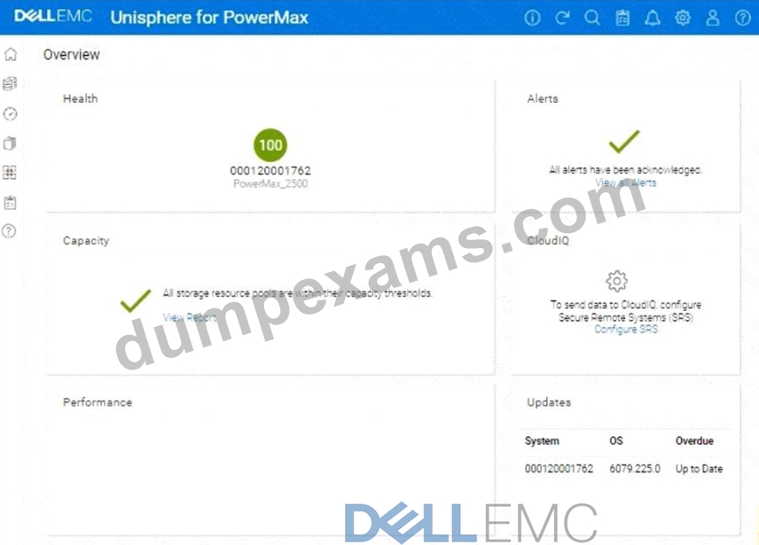
Answer:
Explanation:
See the explanation for step by step solution.
Explanation:
You want a detailed, step-by-step guide on how to add three 100 GB volumes to an existing host and change the service level of the associated storage group from Gold to Platinum on a PowerMax array, using the Unisphere for PowerMax interface shown in the image.
Here's a comprehensive guide, broken down into manageable steps:
Phase 1: Provisioning the New Volumes
Step 1: Log in to Unisphere for PowerMax
* Open your web browser and enter the URL for your Unisphere for PowerMax management interface.
* Log in with your administrator credentials.
Step 2: Navigate to Storage Groups
* In the left-hand navigation pane, click onStorageto expand the storage management section.
* Click onStorage Groupsunder the Storage section. This will display a list of existing storage groups on your PowerMax array.
Step 3: Locate the Target Storage Group
* Identify the storage group that currently contains the host's existing two 100 GB volumes.
* Tip:You can find this by:
* Looking at the "Hosts" tab within each storage group's details. It will list the hosts connected to that storage group.
* If you know the host's name, you might be able to search for it using the Unisphere search bar (if available).
Step 4: Initiate Adding Volumes
* Once you've found the correct storage group, select it by clicking on its name.
* Look for a button or option related to adding volumes. The exact wording might vary slightly depending on your Unisphere version, but it could be:
* "Add to Storage Group"
* "+"(a plus icon, which often signifies adding something)
* "Add Volumes"
* Click this button to start the process of adding new volumes to the storage group.
Step 5: Configure Volume Details
* A new window or panel will appear, allowing you to specify the characteristics of the new volumes.
* Select "Create new volumes"
* Number of Volumes:Enter 3 in the field for the number of volumes.
* Capacity:Enter 100 in the field for the capacity of each volume. Make sure the unit is set to GB.
* Volume Name (Optional):You can give the volumes a specific name or prefix, or you can let Unisphere auto-generate names.
* Service Level:Since the final goal is to move the entire Storage Group to platinum, you can either set this to platinum now or change it for the whole group later.
* Other Settings:Review any other available settings (e.g., thin provisioning, data reduction). In most cases, the default settings should be fine, but adjust them if needed based on your environment's best practices.
Step 6: Execute Volume Creation
* After you've configured all the volume settings, review them carefully to make sure they are correct.
* Click the button to execute the operation. This button might be labeled:
* "Run Now"
* "OK"
* "Finish"
* "Apply"
* Unisphere will start creating the new volumes. This might take a few moments.
Phase 2: Changing the Storage Group's Service Level
Step 7: Navigate Back to Storage Groups
* Once the volume creation is complete, go back to the list of storage groups. You can usually do this by clicking "Storage Groups" in the left-hand navigation pane again.
Step 8: Select the Target Storage Group
* Find the same storage group you worked with in Phase 1 (the one containing the host's volumes).
* Click on the storage group's name to open its properties.
Step 9: Modify the Service Level
* Look for a setting related to the "Service Level." It might be a dropdown menu, a field you can edit, or a link to a separate settings page.
* Change the Service Level fromGoldtoPlatinum.
Step 10: Save the Changes
* Click the button to save the changes to the storage group's service level. This button might be labeled:
* "Apply"
* "Save"
* "OK"
Phase 3: Host-Side Configuration
Step 11: Rescan for New Storage on the Host
* The host needs to be made aware of the newly provisioned storage. The exact process for this depends on the host's operating system:
* Windows:
* OpenDisk Management(diskmgmt.msc).
* Go toAction > Rescan Disks.
* Linux:
* Identify the SCSI host bus numbers (e.g., ls /sys/class/scsi_host).
* Use the command echo "- - -" > /sys/class/scsi_host/hostX/scan, replacing hostX with the appropriate host bus number.
* You might also be able to use tools like rescan-scsi-bus.sh.
* VMware ESXi:
* In the vSphere Client, select the host.
* Go toConfigure > Storage Adapters.
* Select the relevant storage adapter (e.g., your HBA).
* ClickRescan Storage.
Step 12: Initialize, Partition and Mount (if needed):
* Once the host detects the new volumes, you'll need to initialize them, create partitions, format them with a filesystem, and mount them, depending on your operating system and how you intend to use the storage. This is done using the host's operating system tools.
Phase 4: Verification and Monitoring
Step 13: Verify in Unisphere
* Go back to the storage group in Unisphere and check the "Volumes" tab. You should see the three new
100 GB volumes listed along with the original two, and they should all have the "Platinum" service level.
Step 14: Verify on the Host
* Confirm that the host can see and access the new volumes.
Step 15: Monitor Performance
* After making these changes, monitor the performance of the storage group and the application using Unisphere's performance monitoring tools. Ensure that the Platinum service level is meeting your application's requirements
NEW QUESTION # 95
Which Solutions Enabler daemon is responsible forGatekeepermanagement?
- A. storgnsd
- B. storapid
- C. storsrvd
- D. storslpd
Answer: B
NEW QUESTION # 96
What will prevent a LUN from being assigned to a second Storage Group?
- A. One of the Storage Groups is a child group
- B. A LUN can only be assigned to one Storage Group
- C. Storage Groups are already participating in a Masking View
- D. Both Storage Groups have a service level assigned
Answer: B
NEW QUESTION # 97
Which SYMCLI command can be used to create a new TDEV and assign it to a Storage Group in one step?
- A. symcfg
- B. symdev
- C. symaccess
- D. symsg
Answer: B
NEW QUESTION # 98
Refer to the exhibit.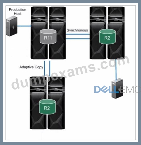
What is the topology shown1?
- A. SRDF/Star
- B. Cascaded SRDF
- C. Concurrent SRDF
- D. SRDF/Metro
Answer: B
Explanation:
Step by Step Comprehensive Detailed Explanation:
The topology shown in the exhibit depictsCascaded SRDF. This SRDF configuration involves three storage arrays (or sites) connected in a chained or cascaded manner.
Here's how it works:
* Primary Site (R1):The production host is connected to the primary storage array (R1).
* Intermediate Site (R2):The primary array (R1) synchronously replicates data to an intermediate array (R2).
* Remote Site (R2):The intermediate array (R2) then asynchronously replicates data to a remote array (also labeled R2 in the diagram).
This cascading setup provides a multi-hop disaster recovery solution, where data is first replicated synchronously to a nearby site for high availability and then asynchronously replicated to a further remote site for disaster recovery.
Why other options are incorrect:
* B. SRDF/Star:SRDF/Star involves a central array replicating to multiple remote arrays in a star-like pattern.
* C. SRDF/Metro:SRDF/Metro is designed for synchronous replication over short distances, typically within a metropolitan area.
* D. Concurrent SRDF:Concurrent SRDF allows multiple SRDF relationships to exist simultaneously for the same device.
References and documents of Dell's public documentation for PowerMax Operate v.2:
* Dell Solutions Enabler 10.0.0 SRDF Family CLI User Guide:This guide provides detailed information about different SRDF configurations, including Cascaded SRDF. You can find this document on the Dell Support website by searching for "Solutions Enabler SRDF Family CLI User Guide."
* Dell PowerMax Family: Essentials and Best Practices Guide:This guide offers a comprehensive overview of SRDF and its functionalities, including various topologies and use cases.
NEW QUESTION # 99
A storage administrator is using SE 10 to query a PowerMax 2000 using symcfg list -dir and wants to seethe number of Cores that are assigned to the front-end emulations What does the storage administrator need to do?
- A. Use the-mode v9x argument for backwards compatibility as some output has been deprecated
- B. Look for CPU instead of Cores as these have been rebranded to allow differentiating between virtual and physical hardware.
- C. Use syraconf igure -version -dir as in SE 10 support for outputs specific to older systems moved to a different command.
- D. Specify the full 12-digit serial number with -sidsoSE 10 understands the output relates to an older system model.
Answer: A
Explanation:
Step by Step Comprehensive Detailed Explanation:
Solutions Enabler (SE) 10 introduces some changes to the output format of certain commands for better clarity and consistency. When querying a PowerMax 2000 (which is based on older VMAX architecture) using symcfg list -dir, you might encounter differences in the output compared to previous SE versions.
To ensure backward compatibility and see the output in the familiar format, you need to use the -mode v9x argument. This tells SE 10 to display the output in the style of SE 9.x, which is compatible with the PowerMax 2000.
Why other options are incorrect:
* B. Look for CPU instead of Cores as these have been rebranded...:While there might be terminology changes, this is not the primary reason for the output difference.
* C. Specify the full 12-digit serial number with -sid so SE 10 understands...:The serial number is not directly related to the output format.
* D. Use syraconfigure -version -dir as in SE 10 support for outputs...:The syraconfigure command is not the correct command for this purpose.
References and documents of Dell's public documentation for PowerMax Operate v.2:
* Dell Solutions Enabler 10.0.0 CLI User Guide:This guide provides detailed information about the symcfg command and its options, including the -mode argument for backward compatibility. You can find this document on the Dell Support website by searching for "Solutions Enabler CLI User Guide."
NEW QUESTION # 100
An administrator is using the Workload Planner feature in Unisphere for PowerMax How does the Planner calculate if the Storage Group workload is stable?
- A. Both calculated values are within the SL-defined response time.
- B. Both calculated values are within a 10-15% threshold of the SL-defined response time
- C. One of the calculated values remains within the SL-defined response time
- D. One of the calculated values is within 10-20% of the SL-defined response time
Answer: A
Explanation:
Step by Step Comprehensive Detailed Explanation:
The Workload Planner in Unisphere for PowerMax helps you analyze and predict the performance impact of adding new workloads to your storage array. It uses sophisticated algorithms to calculate how the addition of a new workload will affect the existing workloads and whether it will violate any service level objectives (SLOs).
To determine if a Storage Group workload is stable, the Planner considers two key calculated values:
* Read Response Time:The predicted read response time of the Storage Group after the new workload is added.
* Write Response Time:The predicted write response time of the Storage Group after the new workload is added.
The Planner compares these calculated values against the service level (SL) defined for the Storage Group. If boththe calculated read and write response times fall within the defined SL response time, the Planner considers the workload to be stable. This means that the new workload can be added without negatively impacting the performance of the existing workloads or violating the SLOs.
Why other options are incorrect:
* A. One of the calculated values is within 10-20% of the SL-defined response time:Both read and write response times must be within the defined SL, not just one.
* B. Both calculated values are within a 10-15% threshold of the SL-defined response time:The threshold is not fixed at 10-15%. The calculated values must be within the actual SL-defined response time.
* C. One of the calculated values remains within the SL-defined response time:Again, both read and write response times need to be within the defined SL.
References and documents of Dell's public documentation for PowerMax Operate v.2:
* Dell Unisphere for PowerMax 10.0.0 Online Help:The online help for Unisphere provides detailed information about the Workload Planner feature, including how it calculates and analyzes workload stability. You can access this help within Unisphere itself or on the Dell Support website.
* Dell PowerMax Family: Essentials and Best Practices Guide:This guide may offer general information about performance management and workload planning in PowerMax, providing context for understanding the Workload Planner's functionality.
NEW QUESTION # 101
Place the steps in the correct order for performing a Non-Disruptive Migration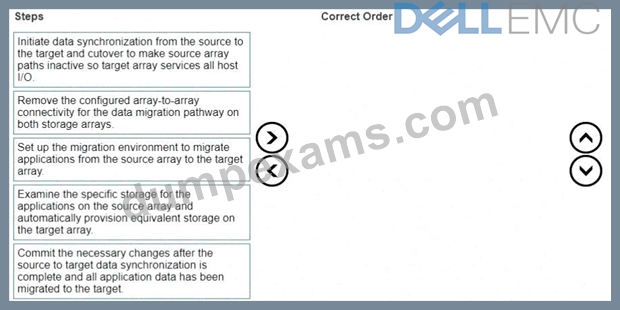
Answer:
Explanation: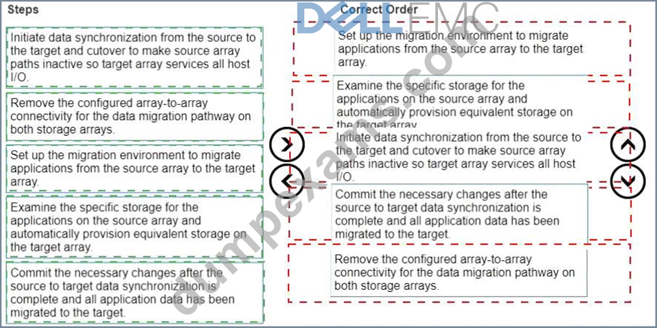
Explanation:
* Set up the migration environment to migrate applications from the source array to the target array.
* Examine the specific storage for the applications on the source array and automatically provision equivalent storage on the target array.
* Initiate data synchronization from the source to the target and cutover to make source array paths inactive so target array services all host I/O.
* Commit the necessary changes after the source to target data synchronization is complete and all application data has been migrated to the target.
* Remove the configured array-to-array connectivity for the data migration pathway on both storage arrays.
Correct Order:
* Set up the migration environment to migrate applications from the source array to the target array.
* Why:This is the initial setup phase, where you configure the necessary settings on both the source and target arrays to enable the migration. This involves actions like:
* Verifying compatibility between the source and target arrays.
* Ensuring that the required licenses are in place (e.g., NDM license).
* Configuring network connectivity (FC or iSCSI) for data transfer between the arrays.
* Examine the specific storage for the applications on the source array and automatically provision equivalent storage on the target array.
* Why:Before migrating data, you need to ensure that the target array has the appropriate storage capacity and configuration to host the applications.
* How:NDM can often automatically provision equivalent storage on the target based on the source configuration. This includes creating storage groups, volumes, and masking views that mirror the source.
* Initiate data synchronization from the source to the target and cutover to make source array paths inactive so target array services all host I/O.
* Why:This is the core of the migration process. Data is copied from the source to the target while the application continues to run. Cutover is the final step where I/O is redirected to the target array.
* How:
* Synchronization:Data is copied in the background.
* Cutover:Once synchronization is complete, a brief cutover is performed. In a well-planned NDM, this cutover is designed to be within the I/O timeout limits of most applications.
* Commit the necessary changes after the source to target data synchronization is complete and all application data has been migrated to the target.
* Why:This step finalizes the migration and makes it permanent.
* What it involves:The migration session is acknowledged and the configuration is finalized on the target array.
* Remove the configured array-to-array connectivity for the data migration pathway on both storage arrays.
* Why:After the migration is complete, the temporary connections used for data transfer between the arrays should be removed to free up resources and maintain a clean configuration.
* What it involves:This typically means removing the FC zones or iSCSI settings that were configured specifically for the NDM process.
NEW QUESTION # 102
Which service has to be manually started first when Unisphere services are down?
- A. SMAS
- B. SMASDB
- C. SYMEVENT
- D. SMI-S
Answer: C
NEW QUESTION # 103
How does Solutions Enabler use Gatekeepers to pass commands to the PowerMax array?
- A. Automatically creates the Gatekeeper and unlocks the device. Processes the system commands; locks and deletes the Gatekeeper
- B. Obtains the Gatekeeper and locks the device. Processes the system commands and unlocks the device
- C. Automatically creates the Gatekeeper and locks the device Processes the system commands; unlocks and deletes the Gatekeeper.
- D. Obtains the Gatekeeper and unlocks the device Processes the system commands and locks the device.
Answer: B
NEW QUESTION # 104
A systems administrator is performing a configuration change on a PowerMax array. Where does the configuration manager perform the change?
- A. MMCS
- B. SYMAPI
- C. Disk drives
- D. Host which performs the change
Answer: A
NEW QUESTION # 105
A VMAX3 array has been configured with two Storage Resource Pools (SRP) Source volumes are assigned to SRP_1 and target volumes are assigned to SRP_2. A TimeFinder SnapVX snapshot of the source volumes is linked to the target volumes in the default mode What will happen when there are new host writes to the source volumes?
- A. Snapshot deltas will be stored in SRP_1
- B. Snapshot deltas will be stored in SRP__2
- C. Snapshot deltas will be stored in the Reserved Capacity of SRP_1
- D. Snapshot deltas will be stored in the Reserved Capacity of SRP_2
Answer: A
NEW QUESTION # 106
A company is preparing for a major product launch and a quarterly compliance audit. Perform a system health check to ensure that the storage array with SID - 1762 is functioning optimally, and also review the compliance status, generate and download the compliance report for all SGs.
Use the simulator to complete these tasks.
Answer:
Explanation:
See the explanation for step by step solution.
Explanation:
Okay, I understand. We need to perform a system health check and review the compliance status for a PowerMax array with SID ending in 1762 using the Unisphere simulator, then generate and download a compliance report.
Here's how you would do it in the Unisphere for PowerMax simulator, based on the provided image and common Unisphere functionality:
Steps:
1. Launch the Simulator and Access the System Health View
* Open Unisphere for PowerMax in your web browser.
* You should already be logged in to the simulator, with the PowerMax array with SID 1762.
* The initialOverviewpage (as shown in the image) provides a good starting point for a health check.
2. Analyze the Overview Page
* Health:The "Health" section displays the overall health status of the array. In the image, it shows "100" with a green checkmark, which indicates that the array is currently healthy.
* Alerts:The "Alerts" section will show if there are any active alerts. In the image, it shows a green checkmark and "All alerts have been acknowledged," meaning no unacknowledged alerts. You can click "View all Alerts" to see the alert history.
* Capacity:The "Capacity" section indicates whether storage resource pools are within their capacity thresholds. The green checkmark and "All storage resource pools are within their capacity thresholds" message indicate that capacity is currently healthy. You can click "View Report" for more details.
* Performance:The "Performance" section is not detailed in the image, but it would typically provide a quick overview of the array's performance.
* Updates:The "Updates" section shows the system's PowerMaxOS code level and whether any updates are overdue. In the image, it shows that the system is "Up to Date."
3. Navigate to the Compliance Section
* In the left-hand navigation pane, click onData Protectionto expand it.
* Click onComplianceunder Data Protection.
4. Review Compliance Status
* The Compliance view will show you the overall compliance status of your storage groups against the defined compliance policies.
* Review the compliance status for each Storage Group.
* Look for any storage groups that are marked as "Non-Compliant."
5. Generate the Compliance Report
* Click on"Generate Report"(or a similarly worded button) within the Compliance view. This might also be represented as an icon in the simulator.
* Select all Storage GroupsSince we need to generate the report for all storage groups.
* Report Format:Choose the desired report format. Common options are usually PDF, CSV, or HTML.
For this simulation, let's assume PDF is available and select it.
* Download the Report:Once the report is generated, there will typically be a"Download"or similar option to save the report to your local system. Click it to download the compliance report.
6. Further Health Checks (Optional):
* Detailed Performance Metrics:You can navigate to thePerformancesection in the left navigation pane (under "Dashboard") to view more detailed performance metrics for various components of the array.
* Hardware Status:You can typically find a "Hardware" section (or similarly named section) that provides information about the physical components of the array (e.g., DAEs, directors, ports).
NEW QUESTION # 107
What is the default size of a Gatekeeper on a PowerMax array?
- A. 3 MB
- B. 6 cylinder
- C. 3 cylinder
- D. 6 KB
Answer: C
NEW QUESTION # 108
What are the Compliance levels tor Storage Groups in Unisphere for PowerMax?
- A. Critical, Marginal. Stable, and No Status
- B. Critical, Marginal. Warning, and No Status
- C. Fatal Critical Warning, and No Status
- D. Fatal. Critical. Stable, and No Status
Answer: A
NEW QUESTION # 109
Four snapshots of a single source volume have been created. The snapshots were created with the same name at 8:00 AM, 10:00 AM, 12:00 PM: and 2:00 PM.
What is the generation number of the snapshot created at 2:00 PM?
- A. 0
- B. 1
- C. 2
- D. 3
Answer: C
Explanation:
Step by Step Comprehensive Detailed Explanation:
In TimeFinder SnapVX, snapshots of a source volume are assigned generation numbers. These numbers indicate the order in which the snapshots were created. The first snapshot taken has a generation number of 0, the second has 1, and so on.
In this case, four snapshots were created at different times:
* 8:00 AM (Generation 0)
* 10:00 AM (Generation 1)
* 12:00 PM (Generation 2)
* 2:00 PM (Generation 3)
Therefore, the snapshot created at 2:00 PM has a generation number of3.
References and documents of Dell's public documentation for PowerMax Operate v.2:
* Dell Solutions Enabler 10.0.0 TimeFinder SnapVX CLI User Guide:This guide provides detailed information about SnapVX features and functionalities, including how generation numbers areassigned to snapshots. You can find this document on the Dell Support website by searching for "Solutions Enabler TimeFinder SnapVX CLI User Guide."
NEW QUESTION # 110
A Storage Group is serving host read/write I/O. The Storage Administrator started an MDM migration and ran a symdm sync -stop command, putting the migration in a CutoverNoSync migration state Where does the customer data in the Storage Group reside?
- A. Only on the source array
- B. Only the target array
- C. On both the source and the target array
Answer: C
Explanation:
Step by Step Comprehensive Detailed Explanation:
In an MDM (Migration for Dell EMC) migration, data is moved from a source array to a target array. When the symdm sync -stop command is issued, it puts the migration into the CutoverNoSync state. This state signifies that:
* Synchronization Stopped:Active data synchronization between the source and target arrays has been stopped.
* Data on Both Arrays:However, the customer data still resides onboththe source and target arrays. This is because the CutoverNoSync state is a transitional state that allows for a controlled cutover to the target array.
The next step would typically involve a cutover operation, where host access is switched to the target array, and the source array is removed from the migration configuration.
Why other options are incorrect:
* A. Only the target array:While the goal is to eventually have the data only on the target, in the CutoverNoSync state, data still exists on both arrays.
* B. Only on the source array:Data has already been partially or fully copied to the target array during the migration process.
References and documents of Dell's public documentation for PowerMax Operate v.2:
* Dell Solutions Enabler 10.0.0 CLI User Guide:This guide provides detailed information about the symdm command and its various options, including the sync -stop command and the CutoverNoSync state. You can find this document on the Dell Support website by searching for "Solutions Enabler CLI User Guide."
* Dell PowerMax Family: Essentials and Best Practices Guide:This guide may offer general information about data migration and the different states involved in the process.
NEW QUESTION # 111
A Fibre Channel Host Bus Adapter (HBA) has failed on a host. You have been tasked with replacing the failed adapter.
What is the correct sequence of steps to successfully replace the adapter?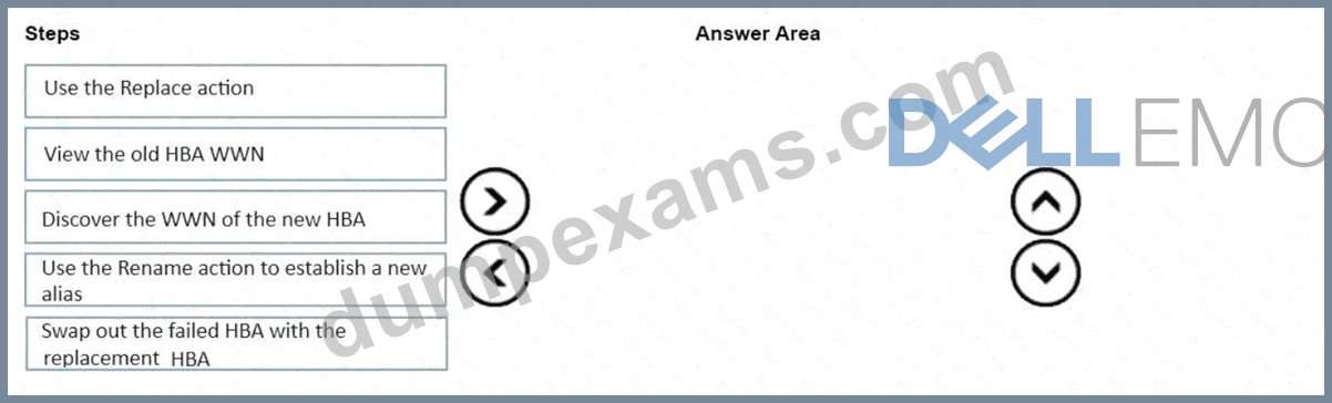
Answer:
Explanation: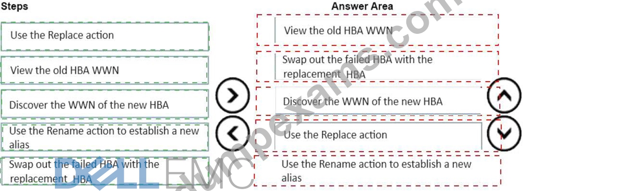
Explanation:
1.view old HBA WWN
2.swap out the old HBA
3.Discover the WWN
4.Use the replace action
5.Use the rename action
NEW QUESTION # 112
What are the two configuration rules that apply to SRDF groups and connections during Non-Disruptive Migrations'?
- A. The source and target arrays are at most one hop away from the control host
- B. DM RDF groups are configured with a minimum of one path
- C. Two DM RDF groups are created per SG migration session
- D. A single array cannot have multiple DM RDF groups
- E. RF and RE ports are supported, with RF ports being selected if both types are available
Answer: A,B
Explanation:
Step by Step Comprehensive Detailed Explanation:
Non-Disruptive Migration (NDM) is a feature in PowerMax that allows you to migrate data between storage arrays without any downtime or disruption to host applications. During NDM, SRDF (Symmetrix Remote Data Facility) is used to replicate data between the source and target arrays. Here are the configuration rules that apply to SRDF groups and connections during NDM:
* A. The source and target arrays are at most one hop away from the control host:The control host, which manages the NDM process, must have direct connectivity to both the source and target arrays.
This ensures efficient communication and control during the migration.
* E. DM RDF groups are configured with a minimum of one path:SRDF groups used for NDM (DM RDF groups) must have at least one active path between the source and target arrays. This ensures that data can be replicated continuously during the migration.
Why other options are incorrect:
* B. Two DM RDF groups are created per SG migration session:This is not a strict requirement. The number of DM RDF groups may vary depending on the configuration and the specific NDM operation.
* C. RF and RE ports are supported, with RF ports being selected if both types are available:While RF and RE ports are supported for SRDF, there's no specific preference for RF ports during NDM. The choice of ports depends on the overall network configuration and availability.
* D. A single array cannot have multiple DM RDF groups:An array can have multiple DM RDF groups if needed for different NDM operations or configurations.
References and documents of Dell's public documentation for PowerMax Operate v.2:
* Dell PowerMax Family: Essentials and Best Practices Guide:This guide provides an overview of NDM and its requirements, including information about SRDF configuration.
* Dell Solutions Enabler 10.0.0 CLI User Guide:This guide provides detailed information about SRDF commands and configuration options, which are relevant for NDM operations.
NEW QUESTION # 113
......
D-PVM-OE-01 Dumps Ensure Your Passing: https://passleader.dumpexams.com/D-PVM-OE-01-vce-torrent.html